What Is a Tapered Roller Bearing?
A Tapered Roller Bearing is designed to manage combined radial and axial loads, making it valuable in vehicles, gearboxes, conveyors, and industrial machinery. Its inner ring, outer ring, and tapered rollers share a common cone geometry. This arrangement directs contact forces toward a single point on the bearing axis. The result is controlled motion under heavy loading.
The design sounds simple. It is not.
The Timken Engineering Manual explains that tapered roller bearings can be adjusted for preload or internal clearance. This adjustment strongly affects stiffness, heat generation, and service life. ISO 281:2007 provides the basic rating-life method, but calculated life is not a promise of field performance. SKF’s Bearing Maintenance Handbook identifies lubrication, contamination, incorrect mounting, and misalignment as frequent causes of premature bearing damage. A clean shaft shoulder, correct grease quantity, and properly seated cup can matter as much as the bearing specification.
Industry data also shows why this component deserves careful selection. The U.S. Department of Energy reports that motor-driven systems represent a major share of industrial electricity use, where friction and maintenance losses can influence operating costs. Tapered roller bearings are not always the most efficient choice. They may create more friction than some alternatives, especially when preload or lubrication is poorly controlled.
This guide explains the bearing’s construction, load behavior, applications, and selection factors. It also considers practical limits. A catalog calculation may look precise, yet dust, shock loads, and installation habits can change the result. That gap between theory and workshop reality deserves attention.
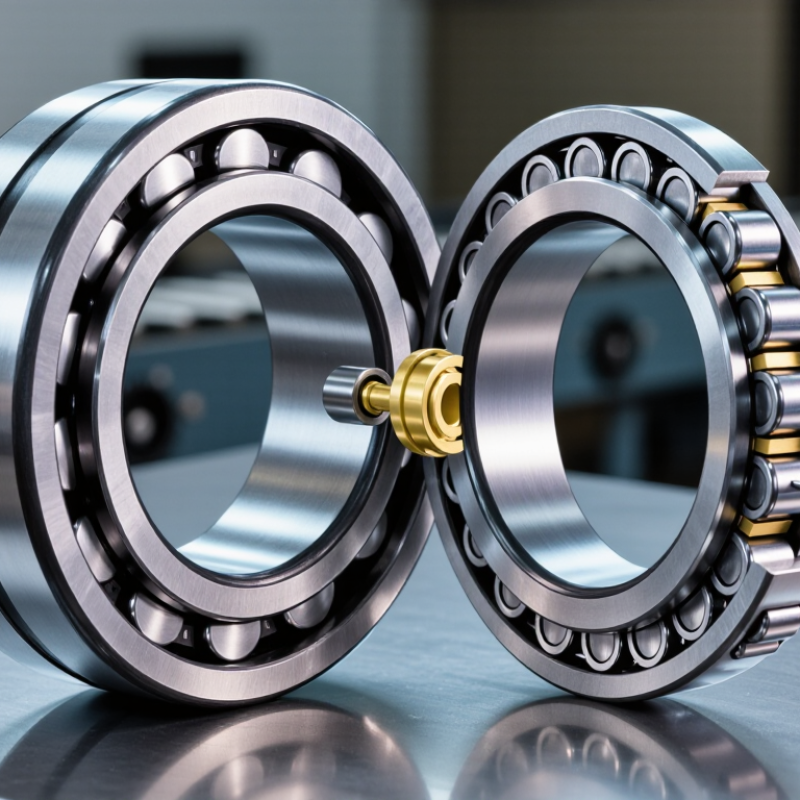
Definition and Core Purpose of a Tapered Roller Bearing
What Is a Tapered Roller Bearing?
A tapered roller bearing supports combined radial and axial loads. Its rollers and raceways form a cone-shaped geometry. This design guides rotating shafts while controlling movement from two directions. The core purpose is accurate load handling, not simple rotation. When a truck hub turns through a corner, the bearing manages weight, steering forces, and impact loads together. The contact remains concentrated along the tapered surfaces.
ISO 281 defines basic rating life as the operating life reached by 90% of identical bearings under stated conditions. That figure supports engineering comparisons, but it does not predict every failure. Lubrication, contamination, preload, alignment, and installation can change real results. The U.S. Department of Energy reports that motor-driven equipment consumes about 69% of industrial electricity in the United States. Small mechanical losses can therefore matter across large facilities. In practice, a bearing may look clean yet show polishing, overheating, or uneven wear. My first inspection assumption would be simple: visual cleanliness is not proof of correct operation.
Tips: Check the load direction before selecting the bearing. Confirm the required radial and axial capacity. Measure shaft and housing fits carefully. Use the lubricant specified for the speed and temperature. After installation, rotate the shaft by hand. Roughness, noise, or abnormal resistance deserves investigation. Record temperature and vibration during early operation. A short baseline often reveals problems before visible damage appears.
What Is a Tapered Roller Bearing? Nominal Boundary Dimensions
Tapered roller bearings use conical rollers and raceways to support combined radial and axial loads. The chart compares nominal bore diameter, outside diameter, and overall width for selected ISO metric bearing designations. Larger dimensions generally provide more space for rollers and can support higher loads when the complete bearing design and operating conditions are suitable.
Key Components and Their Tapered Geometry
What Is a Tapered Roller Bearing?
Key Components and Their Tapered Geometry
A tapered roller bearing contains four working elements: the cone, cup, rollers, and cage. The cone includes the inner ring and roller-guiding rib. The cup forms the outer raceway. Rollers sit between both raceways and carry load through angled contact lines. Their large and small ends follow the bearing’s tapered geometry. Ideally, all raceway and roller axes meet at one point. This creates smooth rolling instead of damaging sliding.
This geometry handles radial and axial loads together. A wheel hub, gearbox shaft, or conveyor pulley can therefore resist both downward force and end thrust. The contact angle controls the balance. A steeper angle generally improves axial capacity, while a smaller angle favors radial loading. ISO 281 defines basic rating life as the revolutions reached by 90% of identical bearings under stated conditions. That figure is useful, but it is not a promise.
Real assemblies are less tidy. Shaft deflection, uneven tightening, contamination, and poor lubrication can shift the load toward one roller. The cage then guides spacing, but it cannot correct every installation error. In practice, I would inspect raceway marks before trusting a calculated life. ISO 76 also provides static load methods, especially where shock or stationary loading matters. Small details matter here. A slight misalignment may produce a polished band on one raceway and early fatigue nearby. Industry calculations remain powerful, yet field evidence deserves equal attention.
How Tapered Rollers Manage Combined Loads
What Is a Tapered Roller Bearing?
How Tapered Rollers Manage Combined Loads
A tapered roller bearing uses cone-shaped rollers between an inner cone and an outer cup. Their angled surfaces create a controlled contact path. This design handles radial loads and axial loads at the same time. Radial force pushes downward, while axial force pushes along the shaft. The rollers transfer both forces through the raceways.
In practical machinery, this matters when a rotating shaft faces changing pressure, not just one steady load. Wheel hubs, gearboxes, and conveyor assemblies often experience this condition. A larger contact angle usually improves axial-load capacity. However, it can increase friction and heat. The correct balance depends on speed, load direction, shaft stiffness, and available lubrication.
The bearing needs careful adjustment.
Too much clearance allows movement and uneven contact. Excessive preload can raise operating temperature and shorten service life. During inspection, I would check roller marks, grease condition, and unusual endplay. A smooth, centered wear pattern is reassuring. A narrow or displaced mark deserves attention. Alignment errors are easy to underestimate, especially after installation. A bearing may rotate quietly at first and still develop damage later. Even experienced technicians can rely too heavily on nominal load ratings. Real operation includes shock, contamination, thermal expansion, and imperfect mounting.
Selection, Installation, and Maintenance Factors
Selecting a tapered roller bearing starts with load direction, speed, temperature, and contamination. Radial and axial loads must be calculated together. ISO 281:2007 defines L10 life as the point where 10% of identical bearings may fail, or 90% survive. Use the basic rating life equation,
L10 = (C/P)^p
but do not treat it as a guarantee. Shock loads, misalignment, and poor sealing can shorten real service life.
Installation demands clean hands, clean tools, and measured force. Press only against the ring being fitted. Never drive through the rollers. Set endplay or preload according to the equipment maker’s specification, then rotate the shaft by hand. It should feel smooth, without a tight spot. Incorrect adjustment can create heat within minutes. I have seen technicians trust torque alone. That shortcut is unreliable because friction changes with lubricant and surface finish.
Maintenance should monitor temperature, noise, vibration, lubricant condition, and visible leakage. A widely cited industry failure-analysis benchmark attributes about 40% of rolling-bearing failures to inadequate lubrication. That figure is a warning, not a universal rule. Follow ISO 15243 damage classifications when examining spalling, smearing, or discoloration. Relubricate by quantity and interval, not habit. ASTM D4378 supports lubricant condition monitoring for industrial equipment. Keep records of operating hours and temperature trends. The imperfect part is prediction: a clean bearing can still fail early when alignment, housing stiffness, or transient loading is misunderstood.